

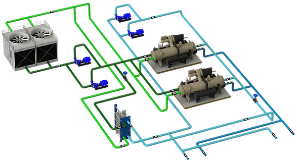
They are the systems that have a decoupling element that separates the primary and the secondary, in such a way that hydraulically what happens in the secondary does not affect the primary.

CONTENTS
1 - TECHNICAL SHEET
2 - GENERAL
This is the most typical hydraulic configuration, so much so that it is sometimes applied even without making much sense, such as systems with a chiller.
This hydraulic configuration is normally projected in a system with 2 or more chillers and variable load variation, enough to partialize production by stopping chillers.
It's a very versatile setup setup-wise, not like theconstant flow coupled systemsand especially those ofvariable flow, VPF
The main objective of this configuration is to hydraulically DISCOUPLE the primary from the secondary, that is, that what happens in the secondary does not affect the primary. However, in most cases this does not happen because a shut-off cock or non-return valve is installed in the bypass COUPLING the primary and secondary.
Another common mistake is not paying attention to themanifold connection order,complicating the optimized management of production. Under this situation, in addition to the loss of efficiency, there are problems in the chillers such as an excessive number of starts and stops and an attempt is made to camouflage the problem by adding inertia, which can alleviate the problem but is not solved.
Today, this configuration with variable flow secondary is the most common and the most sensible and for this reason I dedicate more development to this system. However, it can be found in existing installations with constant secondary flow.
When there is a constant flow, the points to consider in the design and in the control are similar to those indicated in theconstant flow coupled systems, except that now the mixture is produced in the bypass, raising the delivery temperature of the secondary.See more details.
One option to take into account for a secondary constant flow installation isconvert it to variable flow.
3 - COMBINATION OF CHILLERS
As previously mentioned, this is a very versatile combination in terms of configuration:
-
Flow compatibilities between chillers, here it is not essential that all the chillers that make up the plant are compatible in minimum and maximum flow as a system VPF
-
asymmetric configuration; From a design and control system point of view, an asymmetric configuration does not complicate the system at all. Furthermore, an asymmetric configuration is recommended if it is the best option to match production to demand. In an asymmetric configuration you can have:
-
Base chiller, which will have priority in operation. It could be one with very high efficiency, or heat recovery, or any other reason.
-
Peak chiller, the one that will enter the system last, only when it is really necessary, for example the one with the worst efficiency, or the most deteriorated, etc.
-
Pivoting chiller, the one that is used in the sequencing of chillers both in addition and in subtraction to make the transitions between chillers of greater power.
-
Any of the chillers within the system can take a different role, for example a base chiller with heat recovery and lower efficiency can go to peak when recovery is not needed, or a chiller with integrated freecooling.
-
-
Symmetrical configuration, in which all the chillers are the same. At this point it is recommended to take into account that the minimum load of the system is not below the minimum capacity step._d04a07d8-9cd1-3239-8139-6b7d8
4 - CAPACITY MANAGEMENT
In the production control system, in the first place each type of chiller must be considered what role it will play in the order of the sequence, base, peak, pivoting or let's say normal.
If the collector is correctly made and the location of the probes is correct, then an optimized production management can be done, otherwise the system will only be able to do a "simple" sequencing that can present problems in production management.
The control cannot solve the problems that a bad hydraulic design causes, just maybe mask it. Control cannot work miracles.
Addition of chillers:
-
By flow temperature in the collector, under the premise of fewer chillers in operation possible
-
By % load, if you want to take a strategy based on partial load curves
Subtraction of chillers, as long as the delivery setpoint condition is met,
-
By AT on the collector, as long as the order of connections is correct
-
By % load in chillers, check before the subtraction that when removing the next chiller in the sequencing that the rest can be done with the demand.
-
By bypass flow, either measured by flowmeter or by collector probes.
Other functions such as Chiller Water Reset may not have an impact on overall energy savings.
Adjusting production to demand only in terms of thermal power is a concept that is very fashionable, but by itself it presents deficiencies and might not work if other factors are not taken into account.
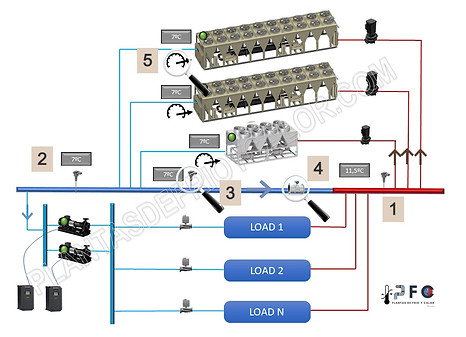
Plant control methods:
-
delivery probe
-
return probe
-
bypass probe
-
bypass flow
-
% chiller load
5 - EXCESS FLOW IN PRIMARY
Why is it necessary to clarify this point?
Because in most cases it is forgotten that a variable flow system must necessarily have excess flow in the primary, that is, a current of cold water that circulates through the collector towards the hot side. The lower this flow rate, the better, as it can be considered wasted pumping energy.
In order to consider that the secondary is a variable flow, it is not only enough to have frequency inverters in the pumps, but the AT must be similar to the design one, and this AT must be equal to the nominal design of the chillers. A low AT could not be considered variable flow but constant.
If the secondary really behaves as a variable, then there is a direct relationship between demand and flow and this is transferred to the primary side, allowing the number of running chillers to be adjusted.
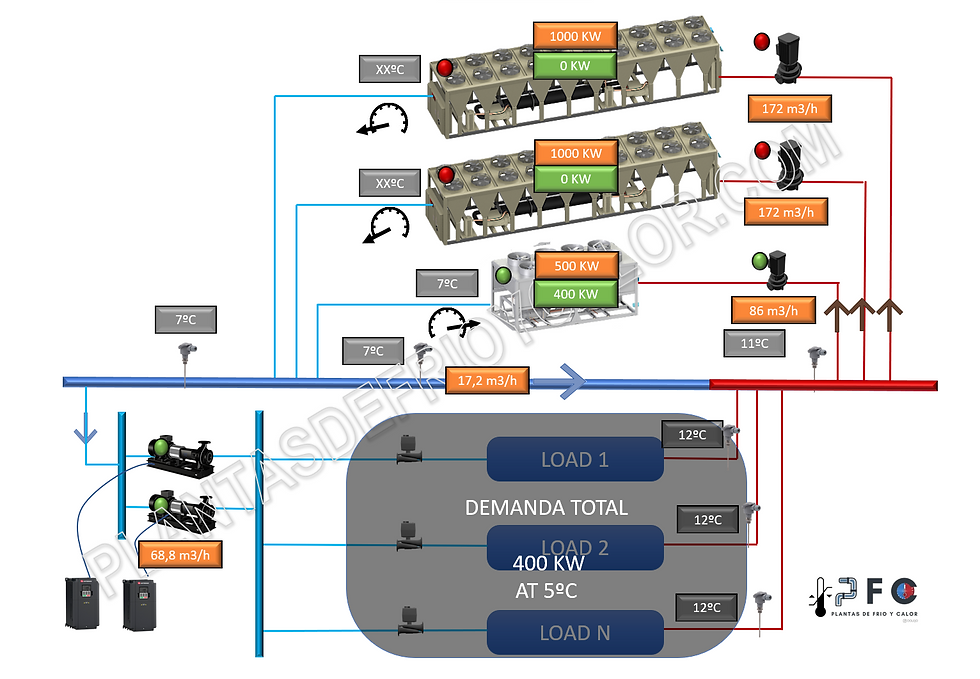
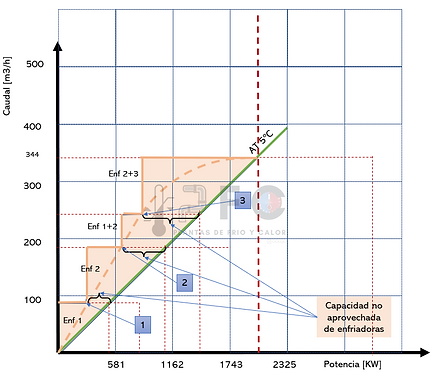
En un sistema con enfriadoras con un AT nominal de 5ºC, Un AT de 5ºC en secundario permite ajustar el número de enfriadoras a la demanda

En un sistema con enfriadoras con un AT nominal de 5ºC, Un AT de 3ºC en secundario rompe el equilibrio entre demanda y número de enfriadoras. En este caso, manteniendo la enfriadora 1 en marcha, hay defecto de caudal en primario y se eleva la temperatura de impulsión de colector.

En un sistema con enfriadoras con un AT nominal de 5ºC, Un AT de 3ºC en secundario rompe el equilibrio entre demanda y número de enfriadoras. En este caso para mantener la consigna en colector es necesario arrancar la unidad 2, no por capacidad sino por caudal
En un sistema con enfriadoras con un AT nominal de 5ºC, Un AT de 5ºC en secundario permite ajustar el número de enfriadoras a la demanda
In the images above there are 3 work scenarios, the same plant configuration and the same demand in secondary, but withdifferent AT in secondaryat partial loads. Let's see what happens:
-
Scenario 1, the secondary AT is 5ºC, the same than the nominal flow rate of chiller selection. _cc781905-5cde-3194-bb3b-136bad5de5cf90 -3194-bb3b-136bad5cf58d_ In this scenario there is a direct relationship between the demand and the number of chillers in operation, there is an excess flow in primary that it circulates through the collector towards the return area, it is mixed with the returns from the installation and the result is mixed water at 11ºC _cc781905-5cde-3194-bb3b -136bad5cf58d_ _cc781905-5cde -3194-bb3b-136bad5cf58d_ _cc7 81905-5cde-3194-bb3b-136bad5cf58d_ _cc781905-5cde-3194 -bb3b-136bad5cf58d_ _cc781905 -5cde-3194-bb3b-136bad5cf58d_ _cc781905-5cde-3194- bb3b-136bad5cf58d_ _cc781905- 5cde-3194-bb3b-136bad5cf58d_ _cc781905-5cde-3194-bb3b-136b ad5cf58d_
-
Scenario 2, the secondary AT is 3ºC while the nominal flow AT for chillers is 5ºC. Chiller 1 supplies 400 KW to the secondary, but now there is a flow defect in the primary and this causes hot water from the returns to mix with cold water. The result is a flow temperature of 8ºC in the secondary. The question is whether this temperature is acceptable for the system. Si la respuesta es no, entonces sólo hay dos formas de proceder: _cc781905-5cde-3194 -bb3b-136bad5cf58d_ _cc781905 -5cde-3194-bb3b-136bad5cf58d_ _cc781905-5cde-3194- bb3b-136bad5cf58d_ _cc781905-5cde-3194 -bb3b-136bad5cf58d_ _cc781905 -5cde-3194-bb3b-136bad5cf58d_ _cc781905-5cde-3194- bb3b-136bad5cf58d_
-
lower the chiller set point below 7ºC to compensate the mixture, with the consequent energy consumption
-
Arrancar la enfriadora 2 y Pasar al escenario 3: _cc781905-5cde- 3194-bb3b-136bad5cf58d_ _cc781905-5cde-3194 -bb3b-136bad5cf58d_ _cc781905 -5cde-3194-bb3b-136bad5cf58d_ _cc781905-5cde-3 194-bb3b-136bad5cf58d_ _cc781905-5cde-3194 -bb3b-136bad5cf58d_ _cc781905 -5cde-3194-bb3b-136bad5cf58d_ _cc781905-5cde-3194- bb3b-136bad5cf58d_
-
-
Scenario 3, the secondary AT is 3ºC while the nominal flow AT for chillers is 5ºC. Although chiller 1 can supply the demand due to capacity, to maintain the excess flow in the primary and not raise the flow temperature in the collector, it is necessary to start chiller 2..
Here is a clear example to control by tryingmatch production to demand in terms of KW without monitoring flows, is a strategy that is not valid if the system does not have a correct AT.
6 - AT PRIMARY AND SECONDARY DESIGN
The primary and secondary must be designed with the same AT so that there is a direct relationship between capacity and demand and number of chillers. If the AT is the same, there would always be excess flow in primary.
Reasons why you don't have the same AT:
-
Error in the design, simply because it has not been taken into account
-
Bad selection of pumps, that for example with everything running there is less flow in primary than the nominal
-
Bad selection of control valves of the terminal units, which causes partial loads not to be regulated correctly and has an AT lower than the design.
CASE 1
-
Constant primary constant flow AT 5ºC
-
Secondary variable flow AT 5ºC
-
Secondary maximum demand 2,000 KW

The green line represents the secondary demand, and therefore the relationship between potential and flow with AT 5ºc]
The blue lines represent the flow and capacity of the chillers. Chiller 1 is started at a constant flow of 86 m3/h. The difference shaded in light blue is the excess flow in primary, that is, the flow of cold water that circulates through the bypass.
When the blue line is cut with the green one (point 1), the flows are equalized, and since the AT on both sides is the same, the power demanded has been equalized with that produced and it is time to start the next equipment.
The operation is repeated, the primary flow increases until it equals the secondary (point 2) and the addition sequence begins
CASE 2
-
Constant primary constant flow AT 5ºC
-
Secondary variable flow AT 5ºC, at partial loads AT 3ºC
-
Secondary maximum demand 2,000 KW
The dashed orange line represents the secondary demand, and therefore the relationship between potential and flow with AT 3ºC at low load and as it increases it is closer to an AT of 5ºC. This is due to poor regulation of the control valves at low load.
The green line represents the flow and power relationship with an AT of 5ºC, in this case for the primary.
The orange lines represent the flow and capacity of the chillers. Chiller 1 is started at a constant flow of 86 m3/h. The difference shaded in light orange is the excess flow in primary, that is, the flow of cold water that circulates through the bypass.
When the orange line (points 1, 2 and 3) intersects with the dashed orange line, it indicates that the primary and secondary flows are equal. At this point there are two ways to act:
•Exhaust the capacity of the chiller up to 100%, but between the dashed line and the green line, there is a flow defect in the primary and therefore a mixture of hot water in the collector.
•If it is necessary to maintain the setpoint in the collector, at this point then the next chiller must be added in the sequencing, even if it still has operating capacity.
The entire area shaded in orange is the excess flow in primary
CASE 3
-
Constant primary constant flow AT 5ºC
-
Secondary variable flow AT 3ºC
-
Secondary maximum demand 2,000 KW
The orange line represents the relationship between secondary flow and power with an AT of 3ºC.
To maintain excess primary flow, the addition operation is carried out by flow and not by chiller capacity, as seen in the previous example.
The difference in this system is when chillers 2 and 3 work, even though there is a lot of capacity available, chiller 1 must be started to compensate for the difference in flow rates. (point 1).
When point 2 is reached, there is no choice but to work with a flow defect, and even with available capacity in production, the system is not capable of maintaining the flow temperature

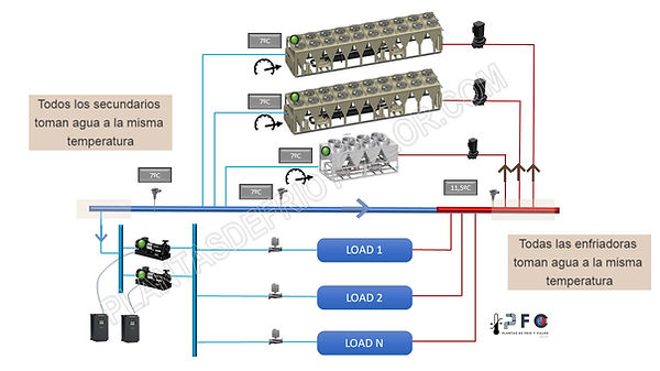
7 - ORDER OF MANIFOLD CONNECTIONS
The order of connections in the manifold is essential in order to achieve an optimized management of the set of chillers.
Many of the problems in existing plants is that the order of connections in the collector is not correct and makes control difficult, so much so that stable operation is not even achieved.
Two simple rules:
-
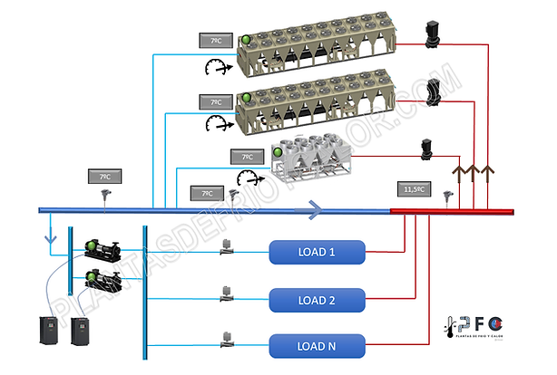
All chillers drink water at the same temperature
-
All secondaries drink water at the same temperature.
Other aspects in collector designs, such as the diameter, vary depending on how the plant will operate.See more.
8 - DESIGN RECOMMENDATIONS
In a configuration of the decoupled type of primary constant flow and secondary variable flow, attention must be paid to the following points:
-
Selection of chillers
-
Nothing to note, those that best suit the circumstances of the project
-
In energy studies, take into account thatchillers in parallel work at the same %of load.
-
-
Chiller Sequencing
-
Addition by flow temperature in collector
-
Addition by % of load if additionally a strategy to work at partial loads is required
-
Subtraction by % load
-
Subtraction by AT collector
-
Bypass flow subtraction
-
-
plant configuration
-
Symmetrical configuration (all chillers are the same) or asymmetrical configuration
-
Peak, base, pivoting chillers
-
collector design
-
Excess flow in primary
-
-
Control of terminal units
-
Pay attention to the selection of V2V to ensure good flow control and therefore an AT similar to the design.This element is vital for the proper functioning of the entire plant.
-