

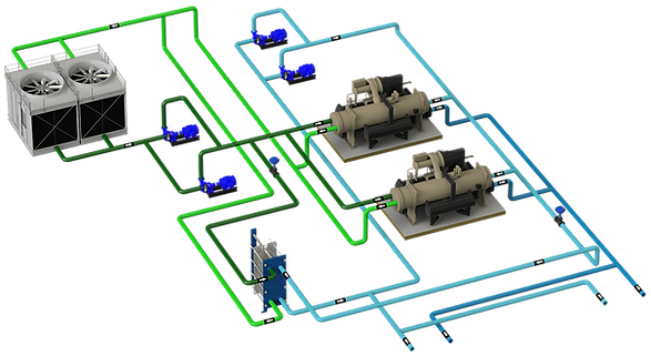
These are the systems that the same pump or group of pumps move the water through the generators and through the rest of the installation to the terminal units.
The distribution is variable flow
CONTENTS
1 - TECHNICAL SHEET
2 - GENERAL
They are more complex systems than parallel systems than constant flow systems and require good planning and understanding of the system on the part of the designer, the control system programmer and the operator.
Highly recommended for systems with demand variation with an initial investment cost lower than coupled systems, since the number of pumps, electrical panel, protections and connections, collectors, etc. is reduced.
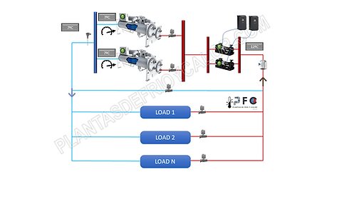
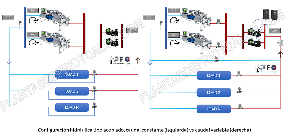
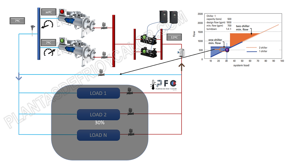
In the diagram below there is a configuration of 2 chillers of the same power and 2 pumps, working at a set point of 7ºC and a return of 12ºC. (Note, if the regulation of the V2V the return should always be the design except for the minimum flow)
This configuration is similar to the constant flow parallel, but now the load regulation in the terminal units is carried out with V2V and therefore now the pumps are inverter. In addition, it is required to provide the installation with additional components:
-
Bypass line, necessary for when the system demand is very low and therefore the flow rate is less than the minimum flow rate of the chiller(s).
-
Flow control through chillers, to establish the minimum and maximum operating ranges.
-
Proportional 2-way valve in the bypass.
-
2-way isolation valve per chiller
This system could have, for example, an additional chiller in reserve mode or an additional pump in reserve, or both, without affecting the operation of the system.
3 - TYPES OF COMPRESSORS, LOW LOAD, RESPONSE SPEED AND FLOW VARIATION
In this configuration, when the demand decreases, first of all the flow decreases, maintaining the AT, so the chillers work with constant AT. Only when the flow limit is exceeded does the by-pass valve open and therefore at this moment the AT of the chiller(s) drops.
Regarding the type of compressor of the chiller and the variation of system load and minimum load, the same must be taken into account as that commented on coupled systems.See here. But taking into account that now there will be a sequencing of chillers.
If the minimum demand is below the minimum capacity of the smallest chiller, it may be necessary to check the system configuration and use the sidecar configuration.
An additional factor to take into account in the selection of chillers is the speed of response to load variation, that is, how the chiller outlet setpoint temperature is affected by the flow rate variation.
Typically, although each manufacturer has some values and it is recommended to consult:
-
Scroll: 10% flow rate variation per minute
-
Screw:
-
10% flow rate variation per minute with a precision of 0.28ºC
-
Variation of 30% of flow per minute with a precision of 1ºC
-
-
Centrifugal:
-
25% flow rate variation per minute with a precision of 0.28ºC
-
Variation of 50% of flow per minute with a precision of 1ºC
-
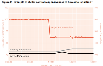
In this graph it can be seen how when the flow varies by 50% (red line), there is a disturbance in the cold water outlet (black line).
After a while it is restored, but the important thing is if the system is capable of working with said temperature variation in the given time. If we are dealing with a system that requires high temperature precision, it must be take into account in the control strategy or if it is necessary to provide the system with a greater volume of inertia.
Source: Trane Engineer Newsletter: the saga continues… Variable-Primary-Flow Systems Revisited
Finally, another aspect to take into account is the variation in flow that chillers allow. We want it to be as large as possible so that this configuration really makes sense.
It is usually said that it should have at least a 50% flow variation with respect to the nominal.
what does it depend on? Well, two factors:
-
exchanger typeTypically, shell and tube evaporators allow for greater load variation than plate heat exchangers.
-
Exchanger and chiller size, most manufacturers have sizes of exchangers that can be installed in chillers of different power and this means that you can find a chiller of the same type with different flow rate . Check with each manufacturer.
4 - CAPACITY MANAGEMENT
In the sequencing of chillers, the following must be taken into account for correct operation:
-
Supply and return temperature.
-
Mainly the flow temperature. As long as the flow temperature is not met, the control system cannot initiate any subtraction logic.
-
The chillers must work with the same setpoint as the setpoint of the system
-
The chiller water reset mode does not apply in this configuration.see more
-
-
% of chiller load.
-
In a subtraction operation, so as not to mistakenly subtract a chiller and have to add a chiller immediately because the demand cannot be met.
-
To operate in the highest efficiency range
-
-
Flow rate through chillers, variable to be incorporated for this system and necessary. It is important NOT to operate:
-
Below minimum flow, there would be freezing problems in the evaporator
-
Above the maximum flow rate, there would be problems due to evaporator wear, for example.
-
-
By-pass flow control
5 - PASS FLOW CONTROL FOR CHILLERS
In a perfectly balanced system working with the AT of the design, the relationship between capacity and flow would be constant. However, the disturbances that the system may have, such as the low AT syndrome, could give rise to the circumstance that maintaining the chiller set point and the appropriate % load, working close to the operating limits of the chillers, and be this the variable that forces the start of the addition or subtraction sequencing.
Based on the fact that flow measurement is crucial in this system, there are several options that the designer must choose, as shown in the graph:

-
General measurement in the circuit, it is useful to have an overview of what is happening, but the detail of each chiller is lost. If all the chillers are equal in capacity and balanced in flow, it could be enough.
-
Individual measurement in chillers, by differential pressure probe. It would allow an individual reading, but with the error range of this system. If the evaporators get dirty, there will be a change in the KV and therefore a measurement error.
-
Individual measurement with a flow meter, undoubtedly the best option but with a higher investment cost.
6 - BY-PASS VALVE
Another differentiating element of a VPF system and which is vital to ensure the success of the system.
Its function is to open the by-pass modulatingly to ensure that it does not operate below the minimum flow rate of the chillers.
It is a valve that can be subjected to the highest differential pressure in the system if it is located in the header.
Therefore, it must be capable of modulating throughout its operating range in all circumstances.
For what flow? A common mistake is to think that it is sized for the flow of one of the chillers.See more.
Where it is located? Three common options:
-
Close to the discharge of chillers and suction of pumps, which presents the greatest energy savings, but requires a valve capable of operating at high pressure. With this location, if the system requires chilled water quickly and there is no circulation through the distribution circuit, there could be a delay.
-
3-way valve in some terminal units, simplifies the operation and the response time in receiving cold water, but against it there is an overconsumption and oversizing of the pumping system.
-
Locate the 2-way valve at the end of the circuit, with the advantage that the valve is subjected to less pressure and helps modulation, but there will be higher pumping costs due to subjecting the circuit to higher pressure during operation.

7 - TURN DOWN RATIO (TD)
It is the relationship between el nominal flow and the minimum flow and is directly related to the control system and the flow through the by-pass valve
In an ideal system, the flow would be proportional to the demand and there would be no flow circulating through the by-pass. Figure 1. This could only be if there was no minimum flow in the chiller.
In a real system with minimum flow, it must circulate through the by-pass and the higher sea this (lower TD Ratio) the greater the flow that must circulate through by-pass:

Source: Trane Engineer Newsletter: peanut butter and jelly Series Chillers and VPF Chiller Plants
Using chillers with very little flow variation, 30% is a TD Ratio of 1.4 implies that when 2 en chillers run in the system and the load drops below 30% and therefore the flow is reduced by 30% in the same way, the bypass valve must open to ensure the minimum flow (orange area).
At this time, it is not possible to subtract a chiller because the demand could not be met with one.
In this example, until 30% of total system demand is reached, the chiller subtraction does not occur. Now if it can be subtracted, then the one that remains running will remain at 70% charge.
As soon as a chiller remains working in the system, it is at 70% flow and therefore water must circulate through the bypass (blue area).
Note that in this configuration, the control system is limiting the chiller not to be subtracted if the % load after the subtraction exceeds 70%.

Sistema con una demanda del 50%, 2 enfriadoras al 50% y caudal por bypass

Sistema con una demanda del 36%, 2 enfriadoras al 36% y caudal por bypass. Límite antes de la sustracción
Sistema con una demanda del 30%, 1 enfriadora al 60% y caudal por bypass.
Sistema con una demanda del 50%, 2 enfriadoras al 50% y caudal por bypass
8 - FLOW FLUCTUATIONS IN THE SYSTEM
The configuration of the pumping system can be of 2 types:
-
Dedicated pump per chiller,
-
pump tandem
In the latter case, it must be taken into account that in the transition processes, the chiller/s running will suffer a flow rate variation. Let's see how in an addition process:
-
The chiller addition is activated, either by:
-
System password has been lost
-
100% capacity of the chiller has been reached or the value of get
-
The maximum flow rate per chiller has been exceeded
-
-
In the chiller activation process, the isolation valve opens
-
At this moment, the flow rate through the chiller is reduced by 50% (assuming equal chillers)
-
Chiller 1 at 100% load and with 50% flow can present micro-freezing until the compressor adapts to the load.
The discharge at start function must be incorporated, and this will lead to a loss of delivery setpoint.
In the first case, with a dedicated pump, there would be a momentary excess pressure in the system:
-
The chiller addition is activated, either by:
-
System password has been lost
-
100% capacity of the chiller has been reached or the value of get
-
The maximum flow rate per chiller has been exceeded
-
-
In the chiller activation process, the isolation valve opens and the pump starts
-
At this time, the system pressure rises until the control PID adjusts the set pressure.
9 - DESIGN RECOMMENDATIONS
Some recommendations to ensure the success of the constant flow coupled system design:
-
Selection of chillers
-
Select for lowest possible minimum evaporator flow limit
-
Selection for highest possible tolerance to large flow rate changes
-
Selection of chillers with HP as similar as possible to nominal flow or incorporate balancing valves
-
Understand the loading and unloading characteristics of each type of chillers
-
bypass flow
-
Correct valve selection, linear modulation and capable of working at high pressure
-
Pay attention to flow measurement
-
Decrease delay times between the control system
-
-
-
Chiller Sequencing
-
Implement download function in start
-
Isolation valve slow opening
-
Let the chillers load almost to 100% before starting the next one
-
Prevent short start-stop cycles
-
-
plant configuration
-
If a VPF is not set in parallel, consider the possibility ofSerial VPFu other settings likesidecar.
-
Same capacity and AP chillers greatly simplify hydraulic system design and control
-
Configuration of the pumping system, dedicated pump or tandem of pumps
-
Asymmetric configuration between chillers and pumps, with independent sequencing
-
-
Control of terminal units
-
Correct selection of 2-way valves in demand control to guarantee a correct AT
-