

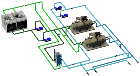
These are the systems that the same pump or group of pumps move the water through the generators and through the rest of the installation to the terminal units.
CONTENTS
1 - TECHNICAL SHEET
2 - GENERAL
They are the simplest systems and are recommended when the system works at full load or with little variation.
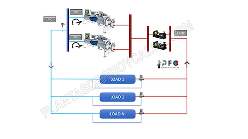
In the scheme below there is a configuration of 2 chillers of the same power and 2 pumps, working at a set point of 7ºC and a return of 11.5ºC.
The system is constant flow and therefore the load regulation is with a 3-way valve. Pumped water passes through both chillers (regulating valve may be required to adjust flow to nominal flow).
This system could have, for example, an additional chiller in reserve mode or an additional pump in reserve, or both, without affecting the operation of the system.

If the system load drops, the installation return temperature would drop and the chillers would partialize compressors to adjust to the demand and this is where the details to take into account would appear.
3 - TYPES OF COMPRESSOR AND MINIMUM LOAD

Type of compressor and minimum load of the chillers:
In this sense, it is necessary to monitor what is the minimum load of the system and that the chillers are capable of working in this range. You have to look for compatibility since:
-
If the load of the installation is lower than the minimum load of the chillers, the compressor(s) will stop and restart immediately, harming the machine and the installation for not maintaining a stable set point. _cc781905 -5cde-3194-bb3b-136bad5cf58d_ _cc781905-5cde-3194- bb3b-136bad5cf58d_ The typical solution is to increase the inertia volume to mitigate this effect, but it only masks a underlying problem.
-
Minimum demand of the installation greater than the minimum load of the chillers, but working at a point of very low efficiency and which, in addition, can present lubrication problems. This could be, for example, chillers with a single non-inverter AC screw compressor. It is very easy to identify this problem in-situ by the sound of the compressor.
4 - CAPACITY MANAGEMENT
In the selection of chillers, therefore, it is necessary to take into account how the equipment behaves at partial loads and project the type of compressor that best suits the demand curve. In this sense, it is convenient not only to look at the partial load indicators such as the SEER, which does give an idea, and to look at the type of technology. At the same SEER, a magnetic levitation equipment finds its maximum efficiency at a different point of partial load than an inverter screw compressor.
Equip the facility with a control system for thesequencingof chillers would be the most reasonable to adjust production to demand and reduce operation and maintenance costs. However, there are a number of factors to take into account in the design.
Points to consider:
Stop chiller, but system has no isolation valve:
As can be seen in the graph, the main problem is that water continues to circulate through the stopped chiller and this will raise the flow temperature in the collector. The question is whether this mixture is acceptable to the system or not.
If it is acceptable, there is no major inconvenience, but if it is not, it can be alleviated in two ways:
-
Chilled water reset;
-
Install shut-off valves per chiller
5 - CHILLER WATER RESET

This is a typical way to make up for mixing.
To do this, the aim is to lower the setpoint of the chiller that is running, but the following must be taken into account:
❌ The temperature drop may have a limit if the installation is not glycoled
❌ Increases the energy consumption of the running equipment
Therefore, it is a strategy that alleviates the problem but it is not the optimal solution.
6 - FLOW EFFECT ON THE PARTIALISATION
Installing shut-off valves per chiller has the advantage of eliminating the mixing effect explained above.
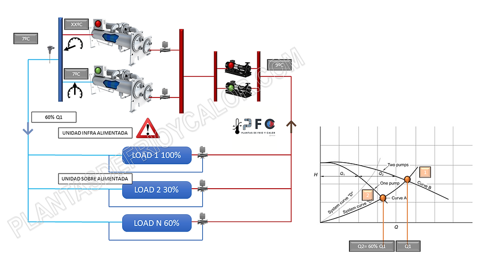
Consequently, the control system should also stop 1 of the pumps and here another important consideration would appear. therisk of leaving terminal units under-powered and therefore not complying with the first principle of design, functionality. Let's see the detail:
In bombs, 1+1 is not 2!!and depending on the characteristic curve of the circuit (Kv) and the pump curves, the sum of the pumps will have a different result. In the graph above, in the circuit with curve A, the working point is indicated as punto 1. When one of the pumps stops, the adjustment of flow and head loss of the circuit passes to be point B, a 40% less flow rate for example.
In a balanced hydraulic circuit in which all the terminal units receive their nominal flow, if the pumping flow is reduced by a certain %, the distribution of water throughout the circuit is done in the same proportion, in this case the flow is reduced_cc781905 -5cde-3194-bb3b-136bad5cf58d_ 40% in all terminal units.
If the load in the terminal units is not reduced in all the units equally and some demand even 100%, for example an HVAC system with different facades and/or uses, or a factory with different processes, there is a risk of leaving units with a flow deficit and therefore not satisfying the cooling needs.
7 - DESIGN RECOMMENDATIONS
Some recommendations to ensure the success of the constant flow coupled system design:
-
Chillers of the same capacity simplify the strategy in the control system.
-
If the chillers are not of the same capacity, they must be compatible in terms of flow with each other if you are going to see sequencing.
-
If the chillers are not of the same capacity, a dedicated pump per chiller is recommended if you are going to see sequencing.
-
If a chiller of different sizes is required and it is very different, it would be convenient to resort to a strategy of the sidecar type.
-
For configurations with tandem pumps in the installation and no dedicated pump, be careful with the lack of flow in the sequence of operation. See download at home
-
Study the demand curve of the installation and project chillers with adequate curves and partialization.
-
The chiller water reset strategy is an option, although not the best, to achieve the set point of the system.
-
Monitor the underfeeding or overfeeding of terminal units when there is pump sequencing.
-
Hire a good control system engineer
-
If the load variation is high and all of the above is a problem in the control system and in the hydraulic installation, think about designing a coupled system with variable flow or a decoupled system.