

As a decoupling element, there are collectors, hydraulic needles and tanks.

CONTENTS
1 - GENERAL
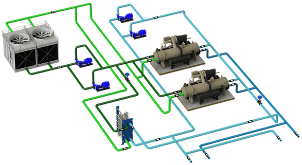
The hydraulic decoupler and its design is key to achieving a stable and "easy to operate" system when you have a decoupled type configuration. So that?
-
Hydraulically separate production from distribution, also known as decoupling the primary and secondary. That is, from the hydraulic point that the primary does not find out what is happening in the secondary. _cc781905-5cde-3194-bb3b-136bad5cf58d9_0 5cde-3194-bb3b-136bad5cf58d_ When you have a collector apparently uncoupled but with shut-off valves closed, or a diameter that is too small, the installation is coupled and that means that the primary and secondary pumps are serially.
-
Have water mixing points where to place the representative probes of the system, with 2 probes the production can be managed correctly
The type of installation, open or closed, determines the design of the uncoupling element, and it is not the same for a hot or cold water installation.
2 - BASIC RULES AND CONSIDERATIONS
Following 2 simple rules, production management can be optimized
-
✅All chillers drink water at the same temperature
-
✅All the secondary ones drink water at the same temperature
-
✅ Recommended design, with slight excess flow in primary. The excess or lack of primary flow must circulate freely through the collector, without the primary and secondary pumps knowing what is happening.
If the previous two are met, with only 2 temperature probes it is enough to monitor what happens in the collector and consequently manage production.
🔎 It is important to note that:
-
➡ The manifold is a zero differential pressure point, there is the same pressure at all points of the manifold
-
➡ All pumps must draw from the manifold, not drive against the manifold. If there are pumps sucking from the collector and others driving against the collector, the installation is coupled.
-
➡ It is recommended that the expansion system be connected to this point, since it is the reference point of the system and all the pumps draw from the manifold.see more

BASIC RULES OF DECOUPLED DESIGN
-
✅All chillers drink water at the same temperature
-
✅All the secondary ones drink water at the same temperature
-
✅ Recommended design, with slight excess flow in primary
3 - SIZING OF THE BYPASS
What criteria should be followed to size the diameter of the bypass?
In the case of continuous collectors, the diameter of the bypass does not have to be the diameter of the general collector, although most of the time a continuous collector is made without changing the section. In this section it refers to the minimum diameter that the bypass should have.
What is sought in the bypass is that there is as little interference as possible, free circulation and that the pumps do not find out what is happening in the system.
In a very small bypass, the primary and secondary pumps are coupled, perhaps not completely but it does cause interference.
In a very large bypass, parallel currents can be produced:
The general criteria are for sizing:
-
Step speed, around 0.5 m / s
-
Linear pressure loss: AP 50 Pa/m
⚙️ For what flow?
Several circumstances can occur:
➡ Primary constant flow, constant secondary:
Although this design option is not the most recommended, if it occurs, all possible scenarios must be studied, for example if the configuration consists of 3 equal equipment (33.3% of the total secondary flow) and the secondary consists of one or more several pumps but that always move the same flow rate, the most unfavorable scenario for the bypass would be to have only 1 chiller running.
➡ Primary constant flow, variable secondary:
Recommended option. The situation that the secondary is stopped and the largest chiller running + 10% would be taken as a reference.
➡ Preferential charging and/or freecooling systems:
If it happens that the equipment placed inpreferential loador infree coolingis capable of meeting all the demand, the production equipment in parallel would not start and therefore all the flow would have to go through the bypass and it must be sized for this flow.
📣 Note: Linear head loss in pipes is not the same for open and closed systems. See the following chart taken from the Carrier Air Conditioning Manual 1970:


4 - RUN COLLECTOR
It is the typical collector in which the aspirations and discharges of primary circuits and secondary circuits are located and it is normally placed horizontally.
The recommended minimum diameter must be such that the welds of the grafts of the larger diameter circuit, both primary and secondary, are feasible to execute. Normally at least one larger diameter.
As previously mentioned, the bypass may or may not have the same diameter as the collector, since its sizing criteria takes into account other factors.
The configuration of a continuous collector is the same for cold or heat plants and special attention must be paid to the distance between connections for the correct mix of water.
⚙️ RECOMMENDED USES:
✅✅ Ice water systems ❄️
✅✅ Hot water systems ☀️
✅✅ Reversible cold and heat systems 🔁
BASIC RULES OF DECOUPLED DESIGN
-
✅All chillers drink water at the same temperature
-
✅All the secondary ones drink water at the same temperature
-
✅ Recommended design, with slight excess flow in primary
5 - HYDRAULIC NEEDLES
It is a hybrid between a vertical collector and a tank, used mainly for heating applications since convention phenomena are less important in chilled water systems.
➡ The needle is positioned vertically with the supply connections at the top of the bottle and the return connections at the bottom of the bottle, to ensure optimal internal convection.
➡ The different outlet and return intakes are generally staggered to avoid any interference and reduce the risk of double circulation, particularly if the cylinder is not equipped with a deflector or a jet breaker.
➡ In the upper part of the bottle a shut-off valve is placed that will allow the isolation of an automatic drain or a manual drain.
➡ The needle is used at the same time as a decanter, and therefore must be equipped with a bleed valve at the bottom that is easily accessible.
➡ A decoupling bottle can be quite large in size and it is preferable to thermally insulate it to avoid unnecessary losses. 5cde-3194-bb3b-136bad5cf58d_
➡ The sizing of a decoupling bottle is done according to the 3D rule, which stipulates:
-
The height of the bottle is determined according to a distance of three diameters between the different tubes.
-
The diameter of the cylinder must be equal to or greater than three times the diameter of the main pipe.
-
An offset of three diameters between the production water inlet and the secondary outlet pipe
-
A distance of three diameters between the highest tube and the top of the bottle.
-
A distance of three diameters between the lower tube and the bottom of the cylinder.
-
A distance of six diameters between the supply connections and the secondary return connections.
This 3D rule allows to establish a circulation speed in the bottle of around 0.1 m/s, while the secondary speed should be around 1 m/s.
⚙️ RECOMMENDED USES:
✅❌ Ice water systems ❄️
✅✅ Hot water systems ☀️
✅❌ Reversible cold and heat systems 🔁

Source: Bipasses et bouteilles hydrauliques pour la regulation, Promoclim, Tome 21 nº3 Mai 1990
6 - SINGLE TANK OPEN CIRCUIT
On many occasions, the installation is of the open circuit type, that is, it is at atmospheric pressure and a single tank is used as a decoupling element, which also serves to increase theinertia volume.
🔎 In this configuration you must take into account:
➡ The warehouse must have a differentiated hot and cold zone, by means of a dividing wall.
➡ The dividing wall must go from the bottom to the top and at the top it must not reach the top so that no water overflows
➡ The primary and secondary pumps must suck from the bottom of the tank to increase the suction pressure and reduce cavitation in pumps.
➡ The selection of pumps and the type must have a very low NPSH, compatible with the real NPSH of the installation.
➡ Compatibility of piping materials, it is an open circuit subjected to constant oxygenation.
⚙️ RECOMMENDED USES:
✅✅ Ice water systems ❄️
❌❌ Hot water systems ☀️
❌❌ Reversible cold and heat systems 🔁

BASIC RULES OF DECOUPLED DESIGN
-
✅All chillers drink water at the same temperature
-
✅All the secondary ones drink water at the same temperature
-
✅ Recommended design, with slight excess flow in primary
7 - SINGLE TANK CLOSED CIRCUIT
As in the previous case, a single tank is used to decouple the primary from the secondary and also have a volume of inertia.
Now the system is pressurized and the tank connections change, with the hot part in the upper zone and the cold part in the lower zone.
⚙️ RECOMMENDED USES:
✅✅ Ice water systems ❄️
✅❌ Hot water systems ☀️, adequate but with nuances. The height/diameter ratio influences stratification,see more.
❌❌ Reversible cold and heat systems 🔁, not suitable since when changing the mode, the order of connections should change

BASIC RULES OF DECOUPLED DESIGN
-
✅All chillers drink water at the same temperature
-
✅All the secondary ones drink water at the same temperature
-
✅ Recommended design, with slight excess flow in primary
8 - DOUBLE TANK OPEN SYSTEM
Similar to the single tank configuration, but now you have one tank for the cold side and one for the hot side.
Between both tanks there is a bypass that must be large enough to be able to absorb excess or insufficient flow. Otherwise, the level of one of the tanks may rise and even overflow with water.
The pump suctions must go in the lower part of the tank to increase the suction pressure and they must have a NPSH compatible with the installation.
⚙️ RECOMMENDED USES:
✅✅ Ice water systems ❄️
❌❌ Hot water systems ☀️
❌❌ Reversible cold and heat systems 🔁

BASIC RULES OF DECOUPLED DESIGN
-
✅All chillers drink water at the same temperature
-
✅All the secondary ones drink water at the same temperature
-
✅ Recommended design, with slight excess flow in primary
9 - DOUBLE TANK CLOSED SYSTEM
Similar to the single tank configuration, but now you have one tank for the cold side and one for the hot side.
Between both tanks there is a bypass that must be large enough not to generate significant pressure loss.
⚙️ RECOMMENDED USES:
✅✅ Ice water systems ❄️
✅✅ Hot water systems ☀️
✅✅ Reversible cold and heat systems 🔁

BASIC RULES OF DECOUPLED DESIGN
-
✅All chillers drink water at the same temperature
-
✅All the secondary ones drink water at the same temperature
-
✅ Recommended design, with slight excess flow in primary
🔎 How is the bypass installed?
Well, it depends on how the system is going to operate, the height at which the bypass must be placed in both tanks is different. For example, let's see for a cold water installation:
Scheme 1️⃣: Excess flow in primary:
The bypass in diagram 1 is represented in the lower part of both tanks to take advantage of the entire volume of water:
In the cold water tank, it is forced to push the cold water discharged from chillers downwards
In the hot water tank, the cold water from the bypass is mixed with the hot return water
Scheme 2️⃣: Primary flow defect:
If in the above configuration at any time during the operation there is a flow defect in the primary, either due to poor regulation of the variable secondary flow or because the demand is greater than the capacity (energy supplied by accumulation) then:
The cold water tank is not capable of supplying all the accumulated energy, the water movements occur in the lower area.
Scheme 3️⃣: Primary flow defect:
To solve the previous problem, the bypass is now connected to the upper part of the cold tank, in such a way that the water is pushed from top to bottom, taking advantage of the entire volume of the tank.
Scheme 4️⃣: Excess flow in primary:
Having the bypass in the upper part of the tank and excess flow in the primary, given the situation that this is above the set temperature, there will be problems to be able to cool this volume in a reasonable time. These situations could be:
-
Start-up of the installation, after a prolonged stop and the tanks are at room temperature
-
Charge cycle (cooling) of inertial volumes after a discharge cycle
 |  |  |
|---|---|---|
 |