

Where should be located the equipment to which you want to give priority in the operation.

CONTENTS
1 - TECHNICAL SHEET
2 - GENERAL
Based on the fact that teams work in parallel at the same % load, or similar, many times there is a team that you want to give priority to in the operation for whatever reason, for example:
-
An absorption machine working with residual heat, and that we are interested in taking advantage of 100% of the cold capacity
-
Aheat recovery chiller,and you want to take advantage of 100% of the available recovery
-
A multitubular chiller, and it seeks to work in moments of simultaneity of demand at the highest possible TER.
-
A water-water heat pump
-
A chiller with a very high performance
-
etc
In many projects, the energy simulation fails because it is considered that in a configuration with chillers in parallel, one team works, for example, at 20% load and the other at 80%, or that in the calculation of a trigeneration the absorption machine works at the same time. 100% when this is not the case because the load is being shared with the rest of the teams.

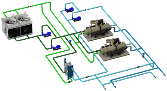
In the scheme shown, there is an absorption machine to which you want to give operation priority since you have a free heat source. The chiller is represented in 2 possible locations:
A) In parallel with chillers 2 and 3 mechanical compression
B) In "sidecar" configuration
3 - % OF LOAD CHILLERS IN PARALLEL IN THE SEQUENCE OF OPERATION
Let's first see how the chillers are distributed in parallel. Case A:

The system is made up of 3 1M chillers, one of which is absorption and the other 2 are mechanical compression.
The three chillers are in parallel and the end user requires that the number 1 chiller, the absorption chiller, is the priority and works at 100% whenever the demand allows it.

The graph represents the distribution of demand among the chillers:
- The red lines are for chiller 1 (absorption)
- The dwellings, for chiller 2
- The blue one for chiller 3
Starting from 0 and with increasing demand up to 1,000 KW, (point A) chiller 1 supplies all the demand.
Upon reaching point A, the control system detects that it must add the next chiller, number 2, and when starting the flow through the bypass doubles, the mixing temperature drops and both are set to fifty%.
Demand continues to increase until point B, 2,000 KW, and the control system detects that the next piece of equipment must start. In the same way as before, the mixing temperature at the collector return point drops and the 3 chillers are put at 66.6% load.
In all the time that chiller 2 has been working between 50% and 100% in the first sequencing and between 66.6% and 100% in the second sequencing, chiller 1 has not been fully utilized and has been you have lost "free cooling".
In the example, the system demands 2,100 KW and since they all take water at the same temperature and all have the same set point, they are all at 70%.
4 - % OF CHILLER LOAD IN PARALLEL AND PREFERENTIAL LOAD IN THE SEQUENCE OF OPERATION

Let's see case B, chiller 1 is now outside the primary, located in the return of the secondary circuit.
The system demand and total installed capacity is the same as in case A.

How is the evolution of demand represented now?
The system demand increases from 0 KW to 1,000 KW (point A). In this section, chiller 1 takes over the entire load, chillers 2 and 3 (and their respective pumps) are stopped, and all the secondary water circulates through the bypass.
When reaching point A and exceeding 1,000 KW, the return water that is mixed with the water that has circulated through chiller 1 is higher than the setpoint, the primary control system detects it and starts chiller 2.
Demand continues to grow up to point B and the control system initiates chiller 3 start-up sequencing, dividing the load between chiller 2 and chiller 3.
The difference with the previous configuration, A, is that now chiller 1 is capable of giving 100% most of the time.
In the example, to supply the 2,100 KW, chiller 1 contributes 1,000 KW, and the remaining 1,100 KW are supplied by chillers 2 and 3 that are at the same % load.
5 - CONTROL SYSTEM
The control system must have 2 control subsystems for production management, one for the system installed in sidecar and another for the control of the chillers in parallel, with the connotations included in the corresponding sections.
For control system in sidecar:
-
Start-stop of the system according to convenience, that is, when required for whatever reason.
-
Constant flow or variable flow of the preferential loading equipment:
-
With constant flow, when the system demand is less than the equipment capacity, there will be a mixture in the circuit.
-
With variable flow, when the system demand is less than the capacity of the equipment, the flow can be reduced so that there is no mixing.
-
-
When the preferential charging equipment is required to work at a certain % load because the maximum efficiency point or another agreed point is sought:
-
Get floating to load or unload the equipment
-
variable flow
-
% load limitation by chiller control module
-
6 - DESIGN CONSIDERATIONS
-
There must be a common section in the return of the installation where all the circuits are collected
-
A collector type design is recommended to connect the preferred charging system.
-
Non-return valves or 2-way control valves must not be installed at the connection point.
-
Choose whether the preferential charging system is done with constant flow or variable flow
-
In uncoupled type configurations, pay attention to the diameter of the collector bypass so that it allows the flow of the preferential charging system to pass when it is sufficient to meet the demand