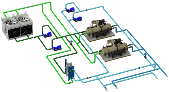

These are modifications that can be made in the configuration when the working range of flow or temperatures is not compatible with the chillers.

CONTENTS
1 - FLOW OUT OF RANGE
It usually happens in process cooling in which the necessary work flow is lower than that of the chiller.
If the load is constant and there is only one computer, the proper configuration would be acoupled system, but due to flow compatibility, a coupled system must be designed.
Excess flow circulates freely through the bypass, cooling the return water from the installation before entering the chiller

2 - TEMPERATURE OUT OF CONSTANT RANGE
When the working temperature of the secondary is higher than what is allowed by the chillers, but low enough to use, for example, a cooling tower.
There are two installation options:
-
Use heat exchanger, differentiating 2 loops with different temperatures
-
Double bypass, with 3-way valve for temperature adjustment.
-
The impulsion of the secondary is mixed with the return to raise the temperature of the entire loop
-
The return water is hotter, but it mixes with the excess cold water that circulates through the main bypass and adapts to the working temperature range of the chiller.
-

3 - TEMPERATURE OUT OF RANGE OCCASIONALLY
This case occurs when the working temperature of the chillers is compatible with the secondary most of the time, but there are occasions when this is not the case, for example:
-
Process with significant load and temperature variation and when there is demand, it can cause the secondary return to rise above the chiller operation.
-
Startup of the installation, after a stop the water has heated up a lot and the mass of water is so high that the chiller is unable to start and stops due to high pressure in the evaporator.
How is it solved?
A loop is installed between the inlet and outlet of the evaporator of the chiller with a 3-way valve, in such a way that when there is very hot water on the return from the installation, the valve opens to take already cooled water and maintains the temperature. inlet to chiller within limits


When it comes to a system in which the return temperature rises a lot and there is no inertia volume or it is scarce, it must be taken into account in the design that then the secondary impulsion water will rise, even up to the return if the 3-way valve has completely separated the chiller loop and therefore all the secondary water circulates through the bypass
The diagram on the left represents the moment in which the temperature limit of the chiller has been exceeded and all the return water circulates through the bypass.
The lower graph represents the supply and return temperature of the system (blue and red). Assuming that the chiller is at 100%, when the return reaches the nominal design value (point A) the flow temperature rises because the chiller is not capable of maintaining the set point. The return water continues to rise until it reaches the operating limit (point B), so the V3V opens to protect the chiller. The system supply temperature is equal to the return since all the secondary water circulates through the bypass.
The orange shaded area would be the energy that should have been accumulated in a given volume and the blue area the system recovery time.

